


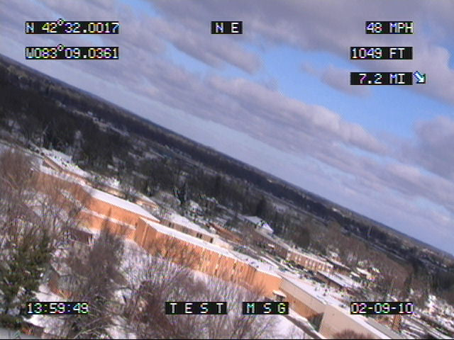
OSD-GPS+™ is an on-screen composite video overlay device in the form factor of a 28 pin .6” dip socket that overlays GPS (Global Positioning System) latitude, longitude, heading (track), speed, altitude, date, and time onto any incoming NTSC or PAL composite video source such as a color video camera. In addition to displaying GPS information, OSD-GPS+™ can also display a user defined message as well as real-time distance and bearing to a user defined waypoint.
OSD-GPS+™ produces a self-generated screen if no video input source is available. All NMEA 0183 compatible GPS receivers are supported.
OSD-GPS+ Specifications:
- Dimensions: 1.54" L x .6” W x .3" H
- Weight: < .1 oz.
- RoHS compliant: Yes
- Input voltage: 5.0 volts DC +/- 5% (150 ma max)
- Operating temperature: -40C to +85C (extended temperature range standard)
- Video format: Composite video Video level: 1 volt peak to peak
- Video impedance: Input 75 ohm, output 75 ohm resistively terminated
- GPS input: NMEA 0183. 4,800 - 38,400 baud. GPRMC and GPGGA sentences.
- Speed format: MPH, KPH, and knots
- Altitude format: Feet and meters
- Heading (track) format: Compass cardinal points (e.g. NW) and degrees
- Time format: UTC with user time zone adjustment
- Date format: mm/dd/yy and dd/mm/yy
- User custom message length: 10 characters
OSD-GPS+ Pinout:

|
Pin #
|
Label
|
Attach To
|
|
1
|
Video In | Video input |
|
2
|
Video Gnd | Video ground (both video input and output share) |
|
3
|
VDC Gnd | DC ground |
|
4
|
+5 VDC | +5 DC source +/- 5% (150ma max.) DO NOT EXCEED 5 VOLTS! If required bypass this pin to ground with a 10uf aluminum electrolytic capacitor |
|
5
|
LOS | Loss of sync of video input Low = video present on input High = no video present on input |
|
6
|
I2C Data | I2C data (future enhancement) |
|
7
|
I2C Clock | I2C clock(future enhancement) |
|
8
|
Reserved | Reserved pin |
|
9
|
Reserved | Reserved pin |
|
10
|
Reserved | Reserved pin |
|
11
|
GPIO 0 | “GPS Fix” status pin When high the attached GPS receiver has a fix with a minimum of 4 satellites. A GPS fix is required for on-screen GPS information to update. Pin can drive external LED with 470 ohm resistor in series. |
|
12
|
GPIO 1 | Unused Pin |
|
13
|
RS-232 Rx | RS-232 (or TTL ) receive |
|
14
|
RS-232 Tx | RS-232 transmit (NOT REQUIRED) |
|
15
|
RS-232 RTS | Unused Pin |
|
16
|
RS-232 CTS | Unused Pin |
|
17
|
RS-232 Gnd | RS-232 ground |
|
18
|
Input 0 | RS-232 baud rate* Input 0 Input 1 Baud No connection No connection 4,800 No connection Pull to ground 9,600 Pull to ground No connection 19,200 Pull to ground Pull to ground 38,400 |
|
19
|
Input 1 | (See Pin 18 Description) |
|
20
|
Input 2 | NTSC or PAL video format* No connection = NTSC Pulled to ground = PAL |
|
21
|
Input 3 | Firmware flash update* Pulled to ground to enter firmware flash update |
|
22
|
Input 4 | “UP” button input Button press should pull input to ground |
|
23
|
Input 5 | “MENU” button input Button press should pull input to ground |
|
24
|
Input 6 | “DOWN” button input Button press should pull input to ground |
|
25
|
Input 7 | “ENTER” button input Button press should pull input to ground |
|
26
|
HSYNC | Horizontal sync output of video input (NOT REQUIRED) Low = video horizontal sync interval High = not video horizontal sync interval |
|
27
|
VSYNC | Vertical sync output of video input (NOT REQUIRED) Low = video vertical sync interval High = not video vertical sync interval |
|
28
|
Video Out | Video output |
OSD-GPS+ Basic System Hookup:
| Pin # | Label | Attach To |
| 1 | Video In | Attach to noise free NTSC or PAL video source such as a camera (NOT REQUIRED) |
| 2 | Video Gnd | Attach to video ground (both video input and output share) |
| 3 | VDC Gnd | DC ground |
| 4 | +5 VDC | +5 DC source +/- 5% (150ma max.) DO NOT EXCEED 5 VOLTS! If required bypass this pin to ground with a 10uf aluminum electrolytic capacitor |
| 13 | RS-232 Rx | Attach to GPS receiver serial output For male DB-9 hookup attach to pin 2 |
| 17 | RS-232 Gnd | Attach to GPS receiver serial ground For male DB-9 hookup attach to pin 5 |
| 28 | Video Out | Attach to video monitor, DVR, etc. |

OSD-GPS+ On-Screen Menu Configuration:
At any time press the "MENU" button (pull input pin to ground) to enter the on-screen menu configuration. The "UP”, “DOWN”, and “ENTER" buttons move the cursor and change the settings. All configuration information is stored in non-volatile memory so information is retained even with loss of power to OSD-GPS+™.| Menu Option | Action / Setting |
| Enable GPS Overlay |
|
| Display Options Menu... | Display the Options Menu |
| Field Formatting Menu... | Display the Field Formatting Menu |
| Save Changes and Exit | Save changes and exit the Main Menu |
| Discard Changes and Exit | Discard changes and exit the Main Menu |
| Menu Option | Action / Setting |
| Screen Layout | Select an on-screen GPS field layout format
|
| Backgnd Frame |
|
| Show Status |
|
| Show Altitude |
|
| Show Ranging |
|
| Show User Msg |
|
| User Message | Enter an optional 10 character on-screen message
|
| Main Menu | Return to Main Menu |
| Menu Option | Action / Setting |
| Altitude |
|
| Speed |
|
| Heading |
|
| Ranging |
|
| Date |
|
| UTC Offset | Time offset from UTC (-12 through +12) e.g. -5 is EDT
|
| Main Menu | Return to Main Menu |
- Establish communications with the attached GPS receiver
- Wait for the GPS receiver fix with a minimum of 4 satellites
- Update the on-screen fields after each valid NMEA GPRMC and GPGGA sentence is received from the GPS receiver
- Check for “MENU”, “UP”, and “DOWN” button presses
| Icon | Status |
|
|
No or invalid communications with the attached GPS receiver |
|
|
The attached GPS receiver does not have a satellite fix |
If the “Show Ranging” option is enabled then distance and bearing information from the current location to the user defined waypoint is displayed in real-time.At any time while there is a GPS fix press the “UP” button to set the current location as the waypoint. Pressing the “DOWN” button will clear the waypoint. It is not necessary to clear the waypoint before setting it again.
OSD-GPS+ Trouble Shooting Tips:
| Problem | Solution |
| Green Power LED will not illuminate OSD-GPS+™ will not turn on |
|
| Blinking Clock icon No GPS information on-screen or fields do not update |
|
| Blinking Satellite Dish icon “GPS Fix” output pin low No GPS information on-screen or fields do not update |
|
| On-screen text is difficult to read |
|
Warranty & Service:
If the product fails to perform as described in our product description or specification, within 1 year from the date of shipment to the buyer, we will repair or replace the product and/or accessories originally supplied. Failure due to improper installation, misuse, abuse or accident is not covered by this warranty. Incidental and consequential damages are not covered by this warranty. The buyer must first obtain a Return Material Authorization number by calling (248) 588-4400, or send email to support@icircuits.com. Ship the defective product (with RMA number) to Intuitive Circuits, 3928 Wardlow Ct., Troy, MI 48083, freight prepaid.