


Description:
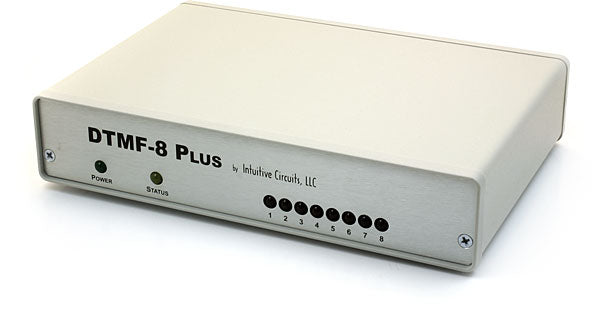
DTMF-8 Plus is a self contained, configurable, DTMF decoder device which permits users to control remotely, via radio or other audio producing source, the on or off state of eight switches. A common application is the remote control of a camera pan/tilt rotor. For larger applications multiple DTMF-8 Plus's can be attached to the same control audio source to control dozens of switches. DTMF-8 Plus supports four modes of operation: latched, momentary, a mixture of latched/momentary, and a mutually exclusive mode. Password security is available to protect from unauthorized access. All configuration information is stored in non-volatile eeprom memory.
Specifications:
- Dimensions: 7 1/4" x 5" x 1 5/8"
- Weight: 20 oz.
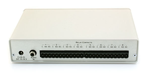
- Input voltage: 12.0 to 14.0 volts DC (360ma max.)
- DC jack: 2.1 mm x 5.5 mm, center tip positive
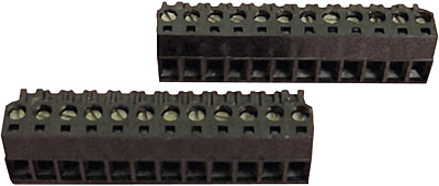
- Terminal plugs: screw type, wire size 12 to 26 AWG
- Operating temperature: -10 C to +70 C
- DTMF receiver: Motorola MC145436AP
- Audio input impedance: 100K Ohms
- Audio input level: .1v to 5.0v
- Relays: SPDT Omron G5V-2-DC12 (sealed)
- Relay contact rating: 4 amps @ 12 volts DC, 1 amp @ 120 volts AC
- Relay contact life: 15,000,000 operations
- Operation modes: 4
- Factory default mode: Mode 1 (latched), no password
- Password length: 0 to 9 digits
- Valid password digits: 0123456789ABCD*#
Connections:
| Connector | Hookup |
| DC 12-14 V: |
|
| AUDIO IN: |
|
| C (1-8) |
|
| NO (1-8) |
|
| NC (1-8) |
|
Configuration:
Configuring DTMF-8 Plus is a simple procedure which programs the device to operate the way that meets the users' application requirements. The custom configuration information is stored in non-volatile eeprom memory so this procedure only needs to be performed once. DTMF-8 Plus can be reconfigured as often as required. To configure DTMF-8 Plus attach a DTMF encoding device such as a DTMF-ENC16 to the "AUDIO IN" jack.(Note: Entering a digit requires the press and release of a key on the DTMF encoder.)
- Apply power to the DTMF-8 Plus. The green "POWER" led will illuminate indicating there is power.
- For four seconds the yellow "STATUS" led will blink. Within that four second window press and release # to enter the configuration mode. While in the configuration mode the "STATUS" led will remain on except when a valid DTMF digit is being decoded.
- Select the desired mode of operation (see the chart below) by entering a 1, 2, 3, or 4.
- If mode 1 or 2 was selected jump to step 7.
- If mode 3 (mixed) was selected then enter the number of relays that will be latched. Valid entries are 1-7. For example pressing 6 will cause relay 1-6 to be latched (like in mode 1), and relay 7 and 8 to be momentary (like in mode 2.) Jump to step 7.
- If mode 4 was selected then enter the power-up "on" relay. Valid entries are 1-8.
- Enter the total number of password digits. Valid entries are 0-9. If no password is required then enter 0 and jump to step 9.
- Enter each digit of the password. Valid digits are: 0123456789ABCD*#.
- The yellow "STATUS" led will turn off. All configuration information is now stored.
DTMF-8 Plus modes of operation:
| Mode 1 | All eight relays are latched.Program mode: Press 1.Relays are turned on (*) or off (#) and remain in that state.e.g. 4* turns on relay 4, 4# turns off relay 4. |
| Mode 2 |
All eight relays are momentary. Program mode: Press 2.The relay is in the on state while the corresponding DTMF tone is being received and in the off state when the DTMF tone is absent. This is useful for controlling devices such as a pan/tilt camera rotor.e.g. While 7 is being pressed relay 7 is on. |
| Mode 3 | Mix of mode 1 and mode 2.Program mode: Press 3 followed by the number of relays to be latched (1-7). The remaining relays are momentary.e.g. After the user enters 3 for this mode and enters 2 for the relay mixture then relays 1 and 2 are latched (like in mode 1), and relays 3-8 are momentary (like in mode 2). |
| Mode 4 | All eight relays are latched and mutually exclusive.Program mode: Press 4 followed by the relay number that will turn on by default whenever the DTMF-8 Plus is powered up (1-8). This mode is for simplified control of latched relays (no need for * or #). The relays are mutually exclusive which means only one of the eight relays will be on. An example application for this is video camera switching where only one source can be selected at a time.e.g. Pressing 8 turns on relay 8. Then pressing 1 turns off relay 8 and turns on relay 1. |
Configuring Additional DTMF-8 Plus Devices:
DTMF-8 Plus is designed to control eight switches (via relays) but it is possible to control more switches by attaching multiple DTMF-8 Plus's to the same incoming audio source and setting a password (more of a device ID in this case) for each unit. For example a remote site may have a video transmitter, camera mounted on a pan/tilt rotor, and outdoor lights. This project would require two DTMF-8 Plus units. The first DTMF-8 Plus (unit 1) controls the video transmitter power, rotor power, and outdoor lights. The second DTMF-8 Plus (unit 2) controls the pan/tilt rotor motion and camera zoom and focus. Unit 1 is programmed for Mode 1 (latched) with a password digit of "A". Unit 2 is programmed for Mode 2 (momentary) with a password digit of "B". To turn on the video transmitter (attached to relay 1 on the first DTMF-8 Plus unit) A, 1, * is entered. To turn on the rotor power (attached to relay 2 on the first DTMF-8 Plus unit) A, 2, * is entered. To pan the camera rotor left (attached to relay 1 on the second DTMF-8 Plus unit) B, 1 is pressed to start the motion and then the 1 key is released to stop the motion. The two DTMF-8 Plus devices ignore commands not directed to them because of their password (unit id.) A password should start with a 9, 0, A, B, C, or D and can be up to 9 digits long.
Operation:
DTMF-8 Plus has front panel led's to indicate the device status. The green "POWER" led indicates the presence of power and will remain on while power is supplied to the unit. The eight red led's numbered 1 through 8 indicate which respective relays are energized (on.) The yellow "STATUS" led blinks during the 4 second power-up sequence and then will illuminate whenever a valid DTMF digit is being decoded. Even though DTMF-8 Plus operates differently depending on which of the four modes of operation the unit was configured for, the optional password entry procedure is the same. The password must be entered for each operation before DTMF-8 Plus will except the relay command. For example, a DTMF-8 Plus that is configured for mode 1 (latched) with a 4 digit password of ABCD requires an entry of A, B, C, D, 1, * to turn relay 1 on and A, B, C, D, 1, # to turn relay 1 off. Alternatively, if no password is configured, a simple 1, * turns relay 1 on and 1, # turns it off.
Warranty & Service:
If the product fails to perform as described in our product description or specification, within 90 days from the date of shipment to the buyer, we will repair or replace the product and/or accessories originally supplied. Failure due to improper installation, misuse, abuse or accident is not covered by this warranty. Incidental and consequential damages are not covered by this warranty. The buyer must obtain a Return Material Authorization by calling (248) 588-4400, and shipping the defective product to Intuitive Circuits, 3928 Wardlow Ct., Troy, MI 48083, freight prepaid. After the warranty expires, we will promptly supply an estimate for the repair cost.