


Description:
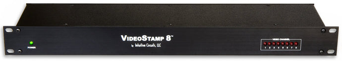
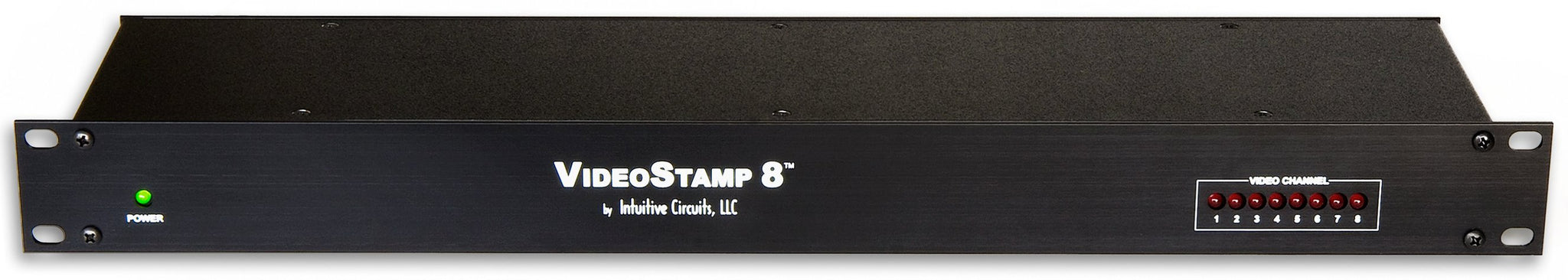
VideoStamp 8™ is an eight channel on-screen composite video character and graphic overlay device with real-time clock. From any RS-232 source, such as a PC, control the display of 30 columns by 12 rows (NTSC) or 15 rows (PAL) of information directly onto an incoming composite video source. VideoStamp 8™ can overlay characters and graphics onto either an incoming video source or self-generated background screen. Each VideoStamp 8™ channel has 256 definable 12 x 18 pixel characters. Graphic images (such a logos) can be imported to create on-screen sprites. VideoStamp 8™ video channels are individually addressable. Up to 32 VideoStamp 8™ devices can be daisy-chained together to allow the addressing of 255 individual video channels from a single RS-232 source.
Included with the VideoStamp 8™ is a 110 VAC wall power supply, 6’ DB-9 serial cable, 4 rack mounting screws, demonstration utility, and font editing software.
Specifications:
- Dimensions:19" x 5" x 1.7" (1U rack unit high)
- Weight: 58 oz.
- Input voltage: 7.5 volts DC (820 ma max.)
- DC plug: 2.1 mm x 5.5 mm, center tip positive
- Operating temperature: -10 C to +70 C
- Text area: 30 columns by 12 rows (NTSC) or 15 rows (PAL)
Due to monitor over-scan a minimum of 26 of the 30 columns and 11 of 12 rows (NTSC) are visible on-screen - Character set:256 definable characters per channel. 12 x18 pixels per character.
- Sprites: 16 definable graphic sprites per channel
- Video level: 1 volt peak to peak
- Video impedance: Input 75 ohm, output 75 ohm resistively terminated
- RS-232 serial or TTL input: 9600 or 19200 baud, 8 data bits, 1 stop bit, inverted data
- Status LED’s: Individual loss of signal status LED’s for each video channel. LED illuminated when video present on input.
- Power up defaults: No video channels selected. Each channel is overlay mode, cleared screen, cursor position top left (0,0), visible text, character blink off, character invert off, character background off
- Video format:Composite video. Any combination of NTSC and PAL video channels can be configured on the same VideoStamp 8™ unit.
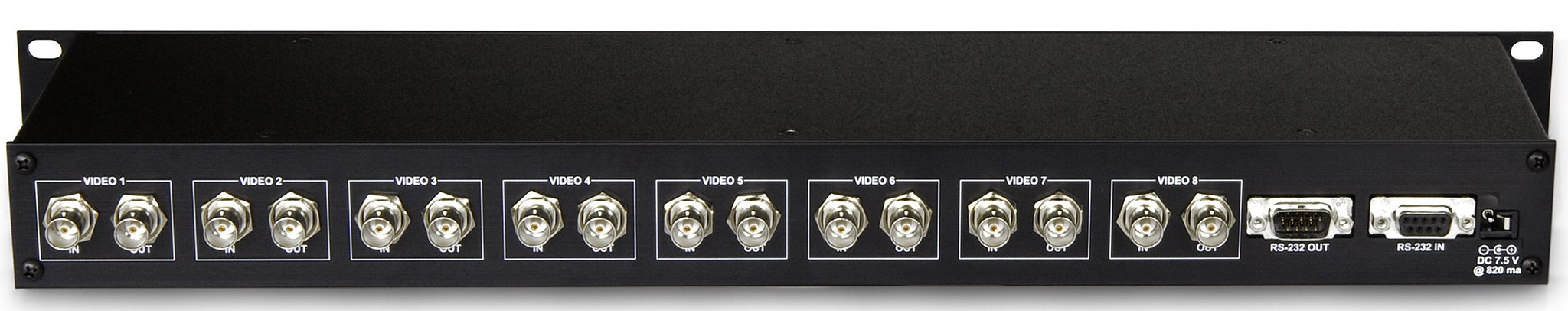
Connections:
All connections to the VideoStamp 8™ are in the rear of the units.
| Connector | Hookup |
| VIDEO IN 1 - 8 |
|
| VIDEO OUT 1 - 8 |
|
| RS-232 IN |
|
| RS-232 OUT |
|
| DC 7.5 IN |
|
Configuration:
VideoStamp 8™ comes configured for 9,600 baud operation with a video channel base address of 00000 (video channel 1 - 8) and single unit (non RS-232 daisy chained) operation. To re-configure these settings VideoStamp 8™ has 8 internal dip switches and a jumper JP1. To access the dip switches and jumper turn power off to the VideoStamp 8™ then remove the 6 screws on the top of the enclosure. The top panel can then be lifted up. DIP’s 1-5 define the VideoStamp 8™ base address in binary. The 5 dips allow for 32 unique values. The factory default setting is 00000. For example if DIP1 - DIP5 are off (base address 0) the device video channels are addressed (via the commands below) 1 - 8. In another example if DIP1 - DIP4 are off, and DIP5 is on then the device base address is 1. The device video channels are addressed (via the commands below) 9 - 16.
| Dip Switch # | Description |
|
1
|
DEVICE ADDRESS MSB |
|
2
|
DEVICE ADDRESS |
|
3
|
DEVICE ADDRESS |
|
4
|
DEVICE ADDRESS. |
|
5
|
DEVICE ADDRESS LSB |
|
6
|
BAUD RATE OFF = 9,600 BAUD [factory default] ON = 19,200 BAUD |
|
7
|
INFORMATION TEST SCREEN (DISPLAYS SYSTEM INFORMATION)OFF = NORMAL OPERATION [factory default] |
|
8
|
VIDEO TYPE (FOR ALL 8 CHANNELS)OFF = NTSC [factory default] |
|
JP #
|
Description |
|
1
|
DAISY CHAIN VIDEOSTAMP 8™ UNITS NOT INSTALLED = MULTIPLE VIDEOSTAMP 8™ UNITS CAN BE CONNECTED TO THE SAME RS-232 SOURCE INSTALLED = ONLY ONE VIDEOSTAMP 8™ CAN BE CONNECTED TO THE RS-232 SOURCE [factory default] |
Communicating with VideoStamp8™
VideoStamp 8™ RS-232 protocol settings are 9600 or 19200 baud, 8 data, 1 stop, no parity, no flow control. Communicating with VideoStamp 8™ requires either sending individual displayable font characters (0x00h – 0xDFh) or sending a command ID value followed by the appropriate number of parameters (see table below.) An individual video channel can be addressed or all video channels can be addressed simultaneously (e.g. to clear the screen). Command values are in hexadecimal (e.g. 0xE0h = 224 decimal).
| Command | Value | # of Params | Description |
| Select Video Channel | 0xE0h | 1 | Select video channel to address (0-255) [1 default] 0 = All video channels simultaneously 1 - 255 = Video channel 1 – 255 |
| Set Video Format | 0xE1h | 1 | Set the video format (0-1) 0 = NTSC 1 = PAL Only required to override dip switch #8 setting |
| Set Overlay Mode | 0xE2h | 1 | Set the video overlay mode (0-2) 0 = Auto switch based on valid video input [default] 1 = Overlay text and graphics with incoming video only (external sync) 2 = Overlay text and graphics with self-generated background screen only (Internal sync) |
| Clear Screen | 0xE3h | 0 | Clear the entire screen with spaces (uses character in font position 00h) |
| Show / Hide Overlay | 0xE4h | 1 | Show or hide the text and graphics overlay (0-1) 0 = Hide text and graphics 1 = Show text and graphics [default] |
| Set Cursor Position | 0xE5h | 2 | Set the cursor position Byte 0 = X (0-29) Byte 1 = Y NTSC (0-12), PAL (0-15) |
| Set Character Blink Attribute | 0xE6h | 1 | Set character blink attribute (0-1) 0 = Off [default] 1 = On Applies to all characters drawn after the command is sent |
| Set Character Invert Attribute | 0xE7h | 1 | Set character invert attribute (0-1) 0 = Normal (white pixels display white, black pixels display black) [default] 1 = Invert (white pixels display black, black pixels display white) Applies to all characters drawn after the command is sent |
| Set Character Background Attribute | 0xE8h | 1 | Set character background attribute (0-1) 0 = Sets the background pixels of the character to the incoming video [default] 1 = Sets the background pixels of the character to the background mode brightness (0xF7h) Note: During internal sync mode, the background attribute behaves as if it is set to 1 Applies to all characters drawn after the command is sent |
| Draw Upper Range Character | 0xE9h | 1 | Draw one upper range font character at the current cursor position (0xE0-0xFF) |
| Draw Sprite | 0xEAh | 1 | Draw one sprite at the current cursor position (0-15) |
| Wait for VBLANK | 0xEBh | 1 | Wait for VBLANK before proceeding (only one of the eight video channels can selected) Byte 0 = Pre-delay in milliseconds (0-128) This is a forced delay before VBLANK detection occurs allowing the user time to send characters to be drawn during VBLANK. |
| Set Screen Horizontal Position Offset | 0xECh | 1 | Set Screen Horizontal Position Offset [default 53] 0 = Farthest left (-32 pixels) 32 = No horizontal offset 63 = Farthest right (+31 pixels) |
| Set Screen Vertical Position Offset | 0xEDh | 1 | Set Screen Vertical Position Offset [default 29] 0 = Farthest up (-16 pixels) 16 = No vertical offset 31 = Farthest down (+15 pixels) |
| Set Date and Time | 0xEEh | 12 | Set the on-board real-time clock mmddyyhhmmss mm = 2 ASCII characters 01-12 dd = 2 ASCII characters 01-31 yy = 2 ASCII characters 00-99 hh = 2 ASCII characters 00-23 mm = 2 ASCII characters 00-59 ss = 2 ASCII characters 00-59 |
| Set Date and Time Display Format | 0xEFh | 2 | Set date and time display format Byte 0 = Date display format (0-1) 0 = mm/dd/yy [default] 1 = dd/mm/yy Byte 1 = Time 12/24 hour display format (0-1) 0 = 24 hour format [default] 1 = 12 hour format |
| Set Time Display Position | 0xF0h | 2 | Set the position to display the on-screen time Byte 0 = X (0-29) Byte 1 = Y NTSC (0-12), PAL (0-15) |
| Set Date Display Position | 0xF1h | 2 | Set the position to display the on-screen date Byte 0 = X (0-29) Byte 1 = Y NTSC (0-12), PAL (0-15) |
| Show / Hide Time | 0xF2h | 1 | Show or hide the on-screen time (0-1) 0 = Hide time [default] 1 = Show time |
| Show / Hide Date | 0xF3h | 1 | Show or hide the on-screen date (0-1) 0 = Hide date [default] 1 = Show date |
| Set Pixel Rise and Fall Time | 0xF4h | 1 | Set pixel rise and fall time—typical transition times between adjacent OSD pixels (0-5) 0 = 20ns (maximum sharpness/maximum cross-color artifacts ) 1 = 30ns 2 = 35ns 3 = 60ns [default] 4 = 80ns 5 = 110ns (minimum sharpness/minimum cross-color artifacts) |
| Set Pixel Switching Time | 0xF5h | 1 | Set pixel insertion mux switching time–typical transition times between input video and OSD pixels (0-5) 0 = 30ns (maximum sharpness/maximum cross-color artifacts ) 1 = 35ns 2 = 50ns 3 = 75ns [default] 4 = 100ns 5 = 120ns (minimum sharpness/minimum cross-color artifacts) |
| Set Row Brightness Black and White Levels | 0xF6h | 3 | Set the row brightness black and white levels Byte 0 = Row number: NTSC (0-12), PAL (0-15) Byte 1 = Character black level % of OSD white level (0-3) 0 = 0% [default] 1 = 10% 2 = 20% 3 = 30% Byte 2 = Character white level % (0-3) 0 = 120% 1 = 100% 2 = 90% [default] 3 = 80% |
| Background Mode Brightness | 0xF7h | 1 | Set background mode brightness for external mode (overlay) character background frame and internal mode (no video) background screen (0-7) 0 = 0% 1 = 7% 2 = 14% [default] 3 = 21% 4 = 28% 5 = 35% 6 = 42% 7 = 49% |
| UNUSED | 0xF8h- 0xFAh | NA | UNUSED |
| Display System Information | 0xFBh | 1 | Display system information on-screen 0 = Information screen* (unit base address, dip switch settings, software version, etc.) 1 = Font screen (font map) * Partial ASCII character font must be installed |
| Soft Reset | 0xFCh | 0 | Reset the VideoStamp 8 to default (power-up) settings |
| Define Sprite (NVM Setting*) (Only one VideoStamp 8 can be connected via RS-232. The device address must be set to 0. JP1 jumper must be installed.) |
0xFDh | 4 | Define a sprite in non-volatile memory Byte 0 = Sprite # (0-15) Byte 1 = Start font table memory position (0-255) Byte 2 = Sprite width in characters (1-30) Byte 3 = Sprite height in characters NTSC (1-13), PAL (1-16) Returns: <cr><lf> (Must wait for before continuing to next sprite) |
| Define Font Character (NVM Setting*) (Only one VideoStamp 8 can be connected via RS-232. The device address must be set to 0. JP1 jumper must be installed.) (Only one of the eight video channels can be selected) |
0xFEh | 56 | Define a character in non-volatile font table memory Each character is 12 x 18 pixels Each pixel consists of 2 bits: 00 = black 10 = white x1 = transparent (pass video though) Byte 0 = Font table position to fill (0-255) Byte 1-54 = 54 bytes – 3 bytes per character row, 18 rows Byte 55 = End byte flag (0xAAh) Returns: <cr><lf> (Must wait for before continuing to next character) |
| Read Data (Only one VideoStamp 8 can be connected via RS-232. The JP1 jumper must be installed.) | 0xFFh | 1 | Read data from one VideoStamp 8 Byte 0 = Read request type 0x00h = Verify RS-232 connection Returns: “ok”<cr><lf> if connected 0x01h = Get firmware version Returns: Firmware version number e.g. “1.01”<cr><lf> 0x02h = Get board dip switch settings Returns: “XXXXXXXX”<cr><lf> (“0” = off, “1” = on) 0x03h = Get all eight video channel input statuses Returns: “XXXXXXXX”<cr><lf> (“0” = no sync, “1” = sync) |
Send 0xE0h, 0x00h - Select all video channels
Send 0xE3h - Clear the entire screen with spaces
Example: Sending Text To Video Channel #1
Send 0xE0h, 0x01h - Select video channel #1
Send 0xE5h, 0x00h, 0x00h - Set cursor position 0, 0
Send “Hello channel 1!” - Send ASCII text
Example: Sending Text To All Video Channels Simultaneously
Send 0xE0h, 0x00h - Select all video channels
Send 0xE5h, 0x00h, 0x00h - Set cursor position 0, 0
Send “Hello all channels!” - Send ASCII text
Example: Sending Blinking Text To Video Channel #4
Send 0xE0h, 0x04h - Select video channel #4
Send 0xE5h, 0x00h, 0x00h - Set cursor position 0, 0
Send 0xE6h, 0x01h - Set character blink attribute (ON)
Send “Blinking text!” - Send ASCII text
Send 0xE6h, 0x00h - Set character blink attribute (OFF)
Example: Drawing Graphic Sprite #2 To Video Channel #8 At Cursor Position 6, 4
Send 0xE0h, 0x08h - Select video channel #8
Send 0xE5h, 0x06h, 0x04h - Set cursor position 6, 4
Send 0xEAh, 0x02h - Draw sprite #2 (defined in font editor normally)
Example: Enable On-Screen Date / Time On All Video Channels
(Note: date / time overlay can only be enabled for all video channels simultaneously on a individual VideoStamp 8™ unit. Individual video channels cannot be enabled with date / time overlay.)
Send 0xF0h, 0x00h, 0x09h - Set the cursor position to display the on-screen time (0, 9)
Send 0xF1h, 0x00h, 0x0Ah - Set the cursor position to display the on-screen date (0, 10)
Send 0xF2h, 0x01h - Show the on-screen time
Send 0xF3h, 0x01h - Show the on-screen date
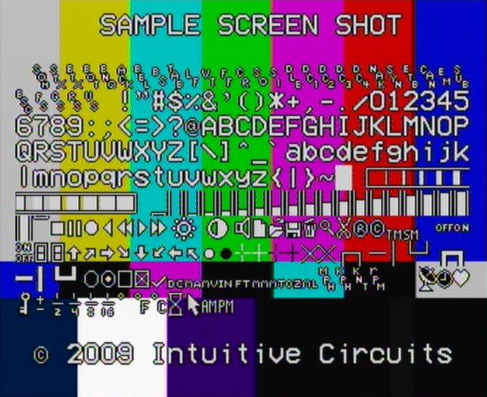
Default Font:
Below is the default font for each VideoStamp 8™ channel. Use the supplied font editor software to create your own or modify the default font. The left column is the high nibble in hexadecimal. The top row is the low nibble in hexadecimal. For example the hourglass character is 0xFCh (252 decimal).

Troubleshooting Tips:
| Problem | Solution |
| Green LED off (unit won’t power up) |
|
| Screen text is skewed or unreadable |
|
| Garbage characters on screen or text not displayed |
|
| Current date / time overlay information not retained with power loss |
|