


Description:
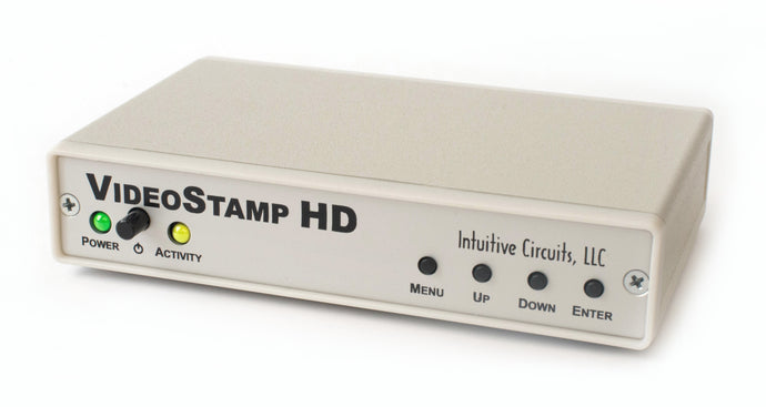
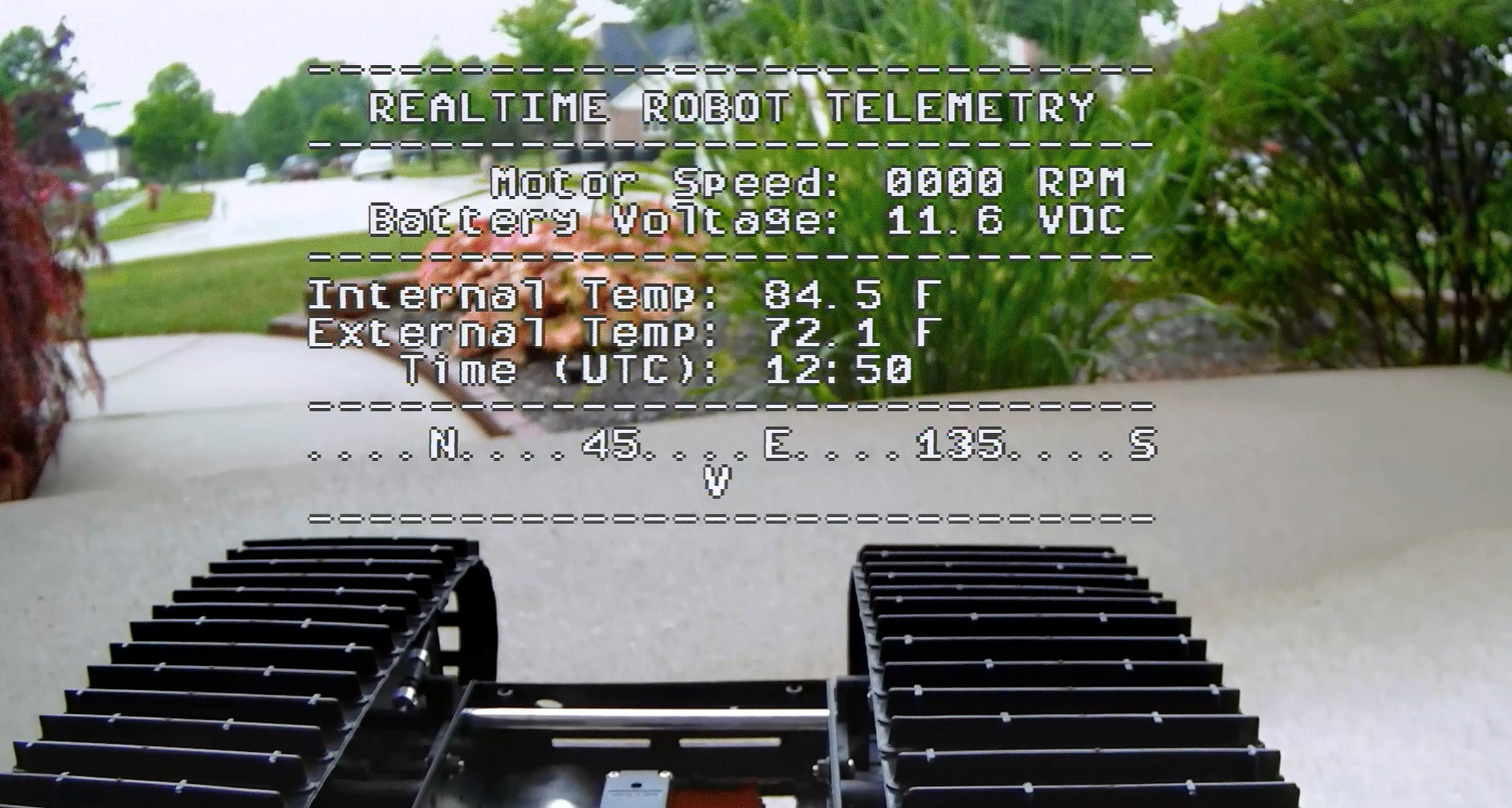
VideoStamp® HD is a standalone on-screen HD video overlay device that overlays user defined text onto any incoming AHD, HD-TVI, and HD-CVI (720p / 1080p) video source such as a video camera. From any RS-232 or TTL source, such as a PC, control the display of 49 columns by 22 rows of information.
Included with VideoStamp® HD is a 110 VAC wall power supply and 6’ DB-9 serial cable.
Specifications:
| Dimensions: | 5 1/2" x 3 1/2" x 1 1/4" |
| Weight: | 10.2 oz. |
| RoHS compliant: | Yes |
| Input voltage: | 8.0 to 14.0 volts DC (150 ma max.) |
| DC plug: | 2.1 mm x 5.5 mm, center tip positive |
| Operating temperature: | -20C to +60C |
| Video formats: | AHD, HD-TVI, HD-CVI (720P and 1080P) |
| Video level: | 1 volt peak to peak |
| Video impedance: | Input 75 ohm, output 75 ohm resistively terminated |
| Text area: | 49 columns by 22 rows |
| RS-232 serial or TTL input: | 4,800 – 38,400 baud, 8 data bits, 1 stop bit, inverted data |
Connections:
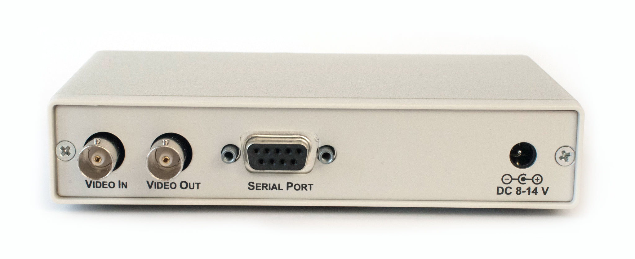
VideoStamp® HD has four connectors:
| Connector | Hookup |
| VIDEO IN | · Attach noise free AHD, HD-TVI, HD-CVI (720P and 1080P) video source |
| VIDEO OUT | · Attach to HD video monitor, DVR, video transmitter, etc. |
| SERIAL PORT | · Attach to 4,800 – 38,400 baud RS-232 or TTL source · Female DB-9 connector type · Pin 2 Serial out (from VideoStamp® HD) · Pin 3 Serial in (to VideoStamp® HD) · Pin 5 Ground |
| DC IN | · +8.0 to +14 volts VDC · 2.1 mm x 5.5 mm DC coax plug, center tip positive |
DIP Switch Configurations:
VideoStamp® HD has 4 internal DIP switches. To access the DIP switches disconnect all cables from the VideoStamp® HD unit then remove the 2 screws from the rear of the enclosure. The rear panel and bezel with the circuit board will slide out.
Note: DIP switches are only checked during power-up.
| DIP # | Description |
| 1 | Reserved |
| 2 | Reserved |
| 3 | Draw Font Screen OFF = Normal Operation ON = Draw Font Screen |
| 4 | Factory Reset OFF = Normal Operation ON = Factory Reset |
Operation:
- Apply power to the VideoStamp® HD
- During power-up the yellow “Activity” LED will blink for 10 seconds
- Data can now be sent via RS-232 or TTL
- Press the MENU button to enter the on-screen menu configuration (see below)
- Simultaneous press the UP/DOWN buttons to configure the incoming video input source (see below)
Configuring the incoming video source:
- The VideoStamp® HD unit must be configured to match the incoming video input source (AHD, HD-TVI, and HD-CVI 720p or 1080p)
- To match the incoming video input source press and release the UP/DOWN buttons simultaneously to cycle through the video options until stable text is visible on-screen (you will see an on-screen menu)
- Press the ENTER button and wait until for the normal operation screen
- The configuration information is stored in non-volatile memory so information is retained even with loss of power to VideoStamp® HD
On-Screen Menu Configuration:
At any time press the MENU button to enter the on-screen menu configuration. The UP, DOWN, and ENTER buttons move the cursor and change the settings. All configuration information is stored in non-volatile memory so information is retained even with loss of power to VideoStamp® HD.
Main Menu:
| Menu Option | Action / Setting |
| Baud Rate | Serial Port baud rate (4,800 - 38,400) |
| Horz Margin | Screen horizontal margin (0 - 5) [Default 2] |
| Vert Margin | Screen vertical margin (0 - 5) [Default 1] |
| Reset Margins | Reset the margins to default |
| Acknowledgment | OFF = Do not respond after command received [Default] ON = Respond with Ack or Nak after command receivedAck (“OK” 0x0d 0x0a)Nak (“ERR” 0x0d 0x0a) |
| RS-232 Diagnostics... | Display RS-232 diagnostics screen (ENTER for next screen, MENU to exit) |
| Save Changes and Exit | Save changes and exit the Main Menu |
| Discard Changes and Exit | Discard changes and exit the Main Menu |
Communication Protocol:
Communicating with VideoStamp® HD requires sending the header ID byte (0xDE), followed by a command value, and appropriate number of data bytes (see table below.) Note values are in hexadecimal (e.g. 0xDEh = 222 decimal).
| Command | Value | # Data Bytes | Description |
| Verify Connection | 0x01 | 0 | Verify connection to VideoStamp HDResponds: "OK"<cr><lf> (regardless of Acknowledgment setting in main menu) |
| Clear Screen | 0x02 | 0 | Clear the entire screen with spacesResponds: "OK"<cr><lf> |
| Clear Row | 0x03 | 1 | Clear one row with spacesParameter 1: Row (0 - 21)Responds: "OK"<cr><lf> |
| Set Margins | 0x04 | 2 | Set screen marginsParameter 1: Horz (0 - 5) [Default 2]Parameter 2: Vert (0 - 5) [Default 1]Responds: "OK"<cr><lf> |
| Draw Text | 0x05 | 2 + TEXT +NULL | Draw on-screen textParameter 1: X Pos (0 - 48)Parameter 2: Y Pos (0 - 21)ASCII text (max 49 chars)NULL terminator (0x00)Responds: "OK"<cr><lf> |
| Configure Blink Text | 0x06 | 2 + TEXT +NULL | Configure blinking text messageParameter 1: X Pos (0 - 48)Parameter 2: Y Pos (0 - 21)ASCII text (max 49 chars)NULL terminator (0x00)Responds: "OK"<cr><lf> |
| Enable Blink State | 0x07 | 1 | Enable the blinking text state Parameter 1: 0 = clear text and stop blinking 1 = draw blink text and start blinkingResponds: "OK"<cr><lf> |
Example: Clear the screen
Send 0xDE 0x02
Example: Draw “Hello” on-screen at cursor X Pos 4, Y Pos 2
0xDE 0x05 0x04 0x02 Hello 0x00