


Description:
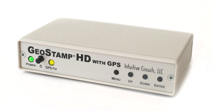
GeoStamp® HD with GPS is a standalone on-screen HD video overlay device that overlays GPS (Global Positioning System) latitude, longitude, heading (track), speed, altitude, date, and time as well as a custom user message onto any incoming AHD, HD-TVI, and HD-CVI (720p / 1080p) video source such as a video camera. GeoStamp® HD with GPS includes an internal high precision GPS receiver and an external GPS antenna.
Specifications:
| Dimensions: | 5 1/2" x 3 1/2" x 1 1/4" |
| Weight: | 10.7 oz. |
| RoHS compliant: | Yes |
| Input voltage: | 8.0 to 14.0 volts DC (180 ma max.) |
| DC plug: | 2.1 mm x 5.5 mm, center tip positive |
| Operating temperature: | -20C to +60C |
| Video formats: | AHD, HD-TVI, HD-CVI (720P and 1080P) |
| Video level: | 1 volt peak to peak |
| Video impedance: | Input 75 ohm, output 75 ohm resistively terminated |
| Speed format: | MPH, KPH, and knots |
| Altitude format: | Feet and meters |
| Heading (track) format: | Compass cardinal points (e.g. NW) and degrees |
| Time format: | UTC with user time zone adjustment |
| Date format: | MM/DD/YY and DD/MM/YY |
| User custom message length: | 10 characters |
Internal GPS Receiver Specifications:
- Receiver: L1 C/A code, 65-channel
- Position Accuracy: 2.5 meters CEP
- Velocity Accuracy: 0.1 meters/sec
- Time Accuracy: 300ns
- Startup Time: 29 second warm/cold start under open sky (average)
- Sensitivity: -161dBm tracking
- Update Rate: 1, 2, 4, 5 Hz (1 Hz default)
- Dynamics: 4G (39.2m/sec2)
- Operational Limits: Altitude < 18,000 meters and velocity < 515 meters/sec (simultaneously)
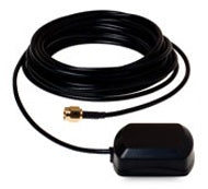
- External Antenna: Active, 3.3 or 5.0 Volts DC with gain up to 30dB and noise figure less than 2db
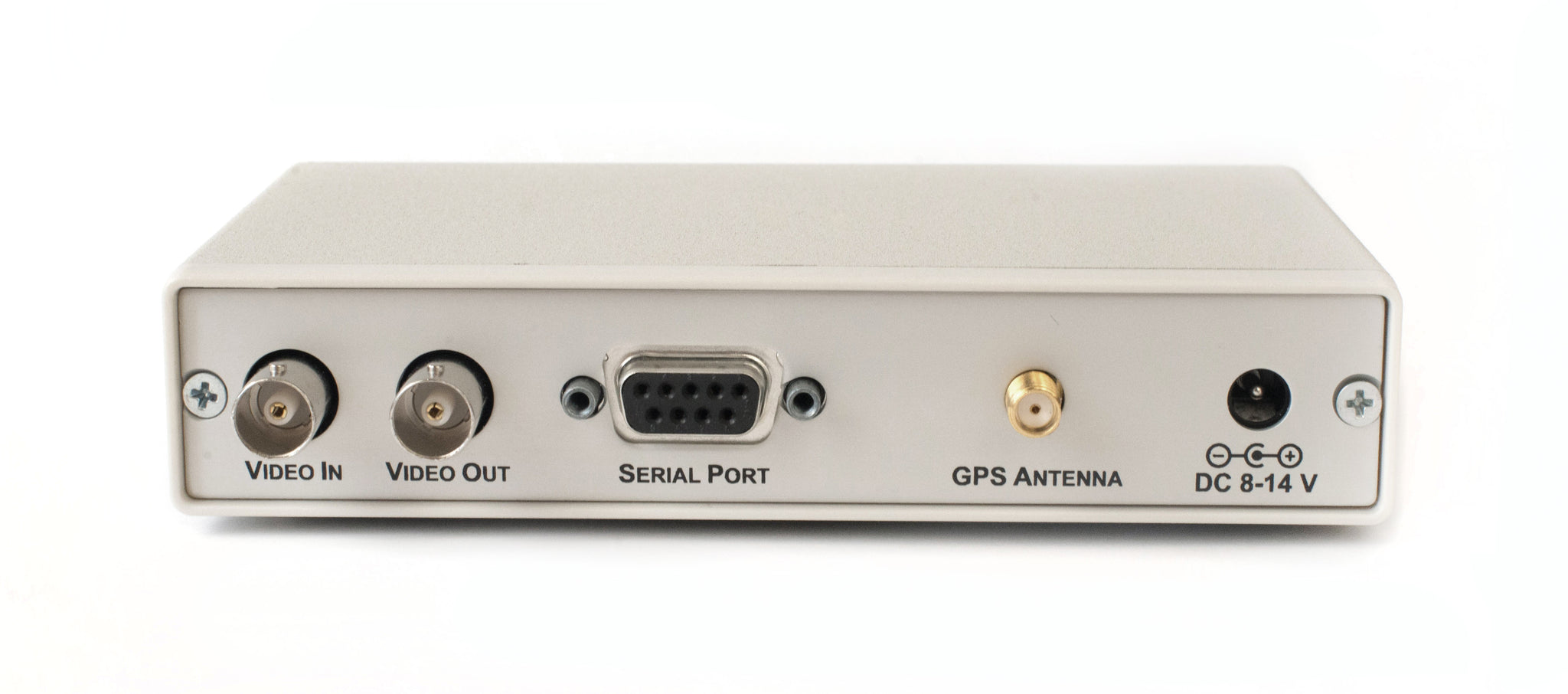
Connections:
GeoStamp® HD with GPS has five connectors
| Connector | Hookup |
| VIDEO IN | · Attach noise free AHD, HD-TVI, HD-CVI (720P and 1080P) video source |
| VIDEO OUT | · Attach to HD video monitor, DVR, video transmitter, etc. |
| SERIAL PORT | · Reserved |
| GPS ANTENNA | · Attach to GPS antenna with SMA male connector · 3.3 or 5.0 Volts DC antenna only |
| DC IN | · +8.0 to +14 volts VDC · 2.1 mm x 5.5 mm DC coax plug, center tip positive |
DIP Switch Configurations:
GeoStamp® HD with GPS has 4 internal DIP switches. To access the DIP switches disconnect all cables from the GeoStamp® HD with GPS unit then remove the 2 screws from the rear of the enclosure. The rear panel and bezel with the circuit board will slide out.
| DIP # | Description | ||
| 1 + 2 | GPS Update Rate | ||
| DIP 1 | DIP 2 | Rate | |
| OFF | OFF | 1 Hz | |
| OFF | ON | 2 Hz | |
| ON | OFF | 4 Hz | |
| ON | ON | 5 Hz | |
| 3 | Reserved | ||
| 4 | Factory Reset OFF = Normal Operation ON = Factory Reset |
Operation:
- Apply power to the GeoStamp® HD with GPS. During power-up the yellow “GPS Fix” LED will blink for 10 seconds.
- An on-screen “X” icon appears if there is no valid communications with the internal GPS receiver
- An on-screen “?” icon appears if there is a valid connection to the internal GPS receiver but no satellite fix
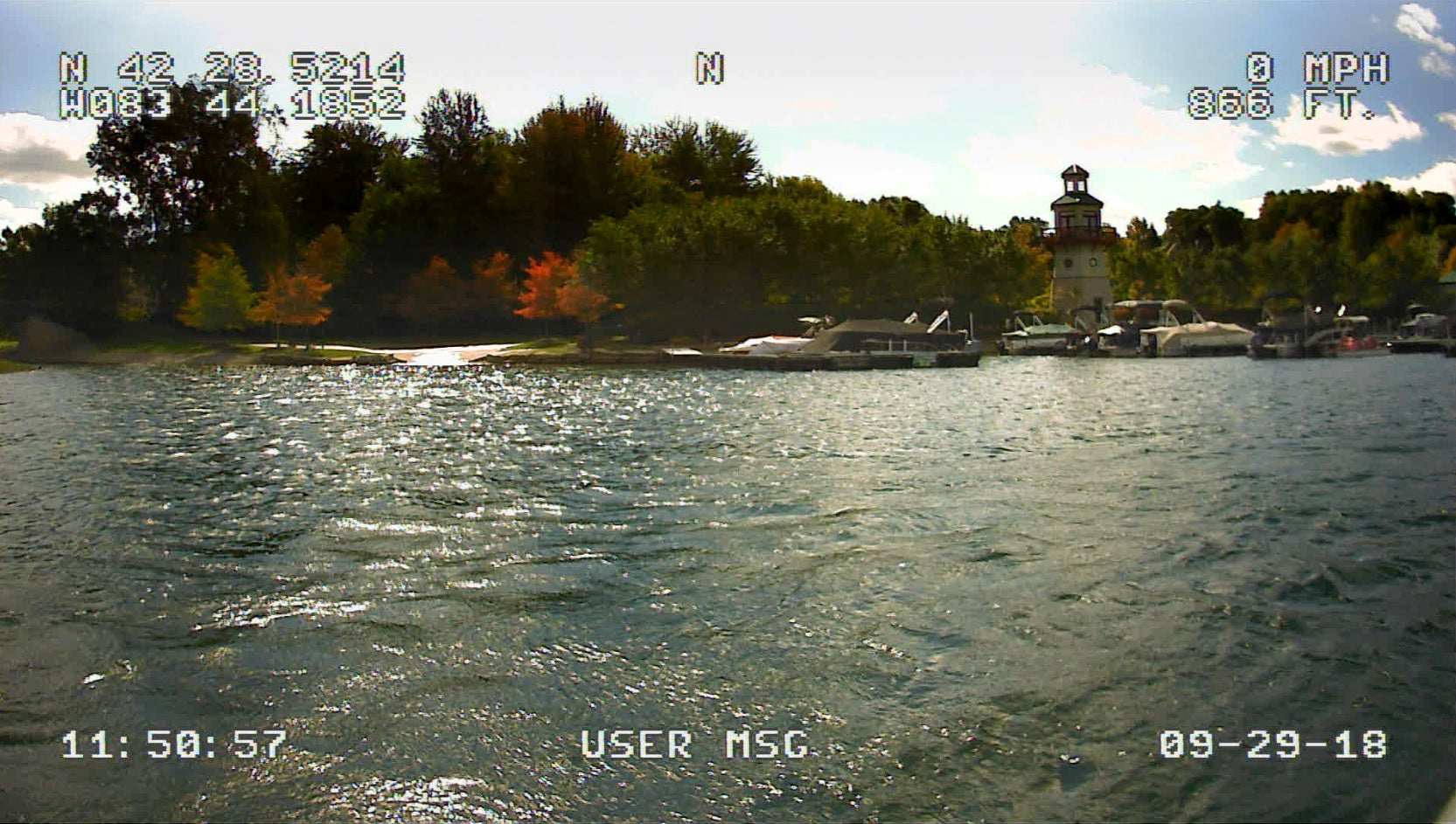
- The on-screen GPS fields will update after each valid NMEA sentence is received from the internal GPS receiver. The yellow “GPS Fix” LED will illuminate.
- Simultaneous press the UP/DOWN buttons to configure the incoming video input source (see below)
- Press the MENU button to enter the on-screen menu configuration (see below)
Configuring the incoming video source:
- The GeoStamp® HD with GPS unit must be configured to match the incoming video input source (AHD, HD-TVI, and HD-CVI 720p or 1080p)
- To match the incoming video input source press and release the UP/DOWN buttons simultaneously to cycle through the video options until stable text is visible on-screen (you will see an on-screen menu)
- Press the ENTER button and wait until for the normal operation screen
- The configuration information is stored in non-volatile memory so information is retained even with loss of power to GeoStamp® HD with GPS
Status Icon:
If the “Show Status” option is enabled (by default) the following icons may appear:| Icon | Status |
| X | No or invalid communications with the internal GPS receiver |
| ? | The internal GPS receiver does not have a satellite fix |
“GPS Fix” LED:
The yellow “GPS Fix” LED illuminates when the internal GPS receiver has a fix with a minimum of 4 satellites. A GPS fix is required for on-screen GPS information to update.
On-Screen Menu Configuration:
At any time press the MENU button to enter the on-screen menu configuration. The UP, DOWN, and ENTER buttons move the cursor and change the settings. All configuration information is stored in non-volatile memory so information is retained even with loss of power to GeoStamp® HD with GPS.
Main Menu:
| Menu Option | Action / Setting |
| Enable GPS Overlay | OFF = Display the overlay text ON = Pass video through without displaying the overlay text |
| Display Options Menu... | Display the Options Menu |
| Field Formatting Menu... | Display the Field Formatting Menu |
| GPS Settings Menu... | Display the GPS Settings Menu |
| Save Changes and Exit | Save changes and exit the Main Menu |
| Discard Changes and Exit | Discard changes and exit the Main Menu |
Display Options Menu:
| Menu Option | Action / Setting |
| Screen Layout | On-screen GPS field layout formats · Standard - Fields are displayed on the top and bottom of the screen · Top - Fields are displayed on the top of the screen · Bottom - Fields are displayed on the bottom of the screen · Left - Fields are displayed on the left side of the screen · Right - Fields are displayed on the right side of the screen · Custom - Future enhancement |
| Show Status | OFF = Do not display the GPS receiver status on-screen ON = Display the GPS receiver status on-screen |
| Show Altitude | OFF = Do not display altitude on-screen ON = Display altitude on-screen |
| Show User Msg | OFF = Do not display the user defined message on-screen ON = Display the user defined message on-screen |
| User Message | Enter an optional 10 character on-screen message · MENU button to decrement cursor position · ENTER button to increment cursor position · UP / DOWN buttons to cycle through characters |
| Download Custom Layout… | Future enhancement |
| Main Menu | Return to Main Menu |
Field Formatting Menu:
| Menu Option | Action / Setting |
| Altitude | Altitude formats · Meters · Feet |
| Speed | Speed formats · Meters · Feet |
| Date | Date formats · MM-DD-YY · DD-MM-YY |
| UTC Offset | Time offset from UTC (-12 through +12) e.g. -5 is EDT · ENTER button to increment value |
| Main Menu | Return to Main Menu |
GPS Settings Menu:
| Menu Option | Action / Setting |
| Diagnostics... | Display GPS diagnostics screen |
| Main Menu | Return to Main Menu |