


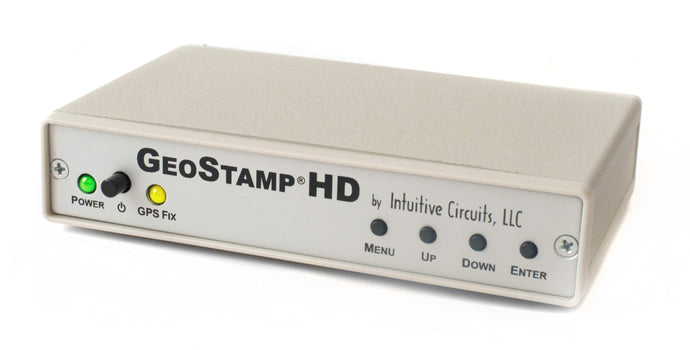

Description:
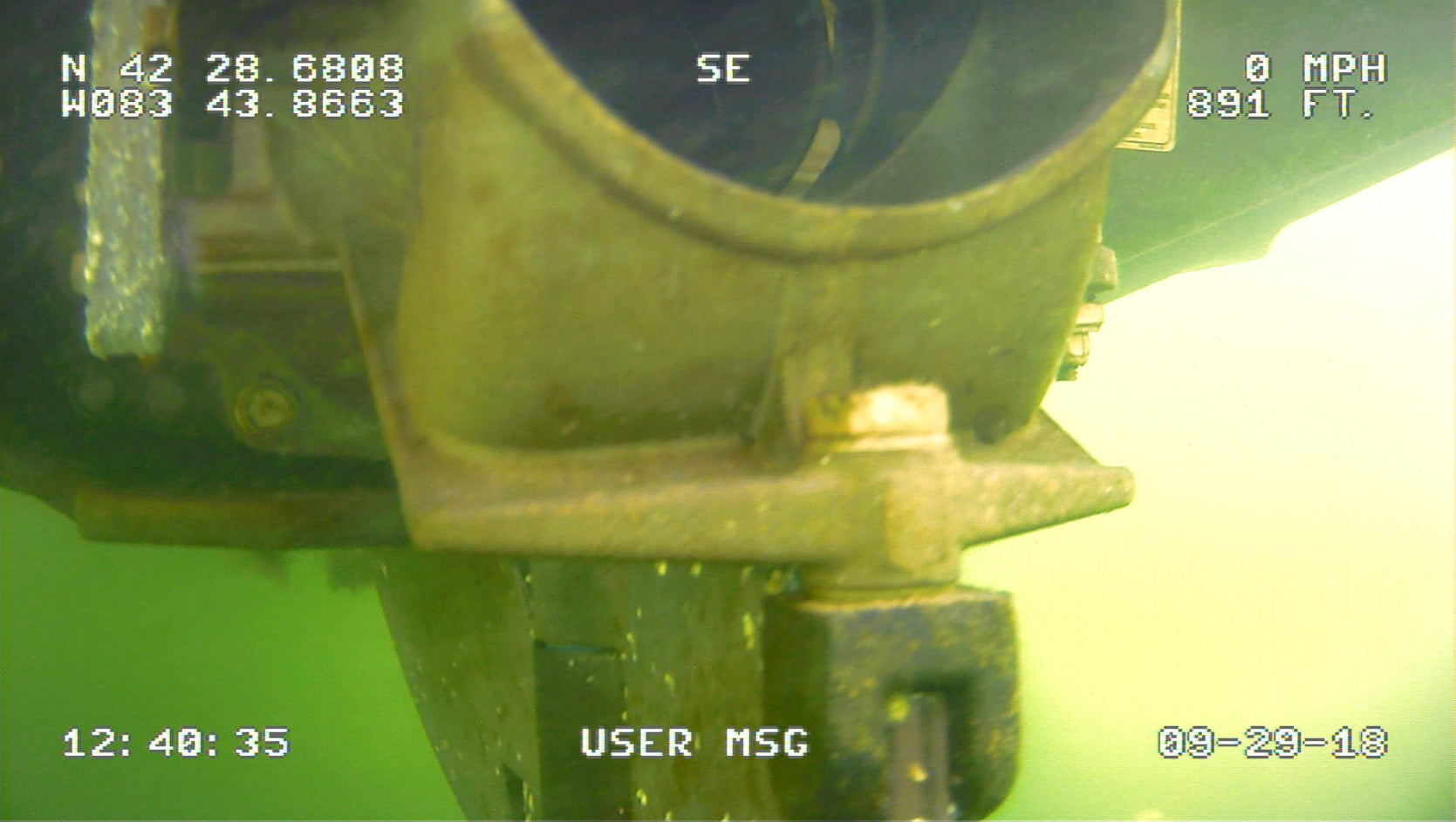
GeoStamp® HD is a standalone on-screen HD video overlay device that overlays GPS (Global Positioning System) latitude, longitude, heading (track), speed, altitude, date, time, and depth below transducer as well as a custom user message onto any incoming AHD, HD-TVI, and HD-CVI (720p / 1080p) video source such as a video camera. All RS-232 NMEA 0183 compatible GPS receivers are supported.
Specifications:
| Dimensions: | 5 1/2" x 3 1/2" x 1 1/4" |
| Weight: | 9.7 oz. |
| RoHS compliant: | Yes |
| Input voltage: | 8.0 to 14.0 volts DC (150 ma max.) |
| DC plug: | 2.1 mm x 5.5 mm, center tip positive |
| Operating temperature: | -20C to +60C |
| Video formats: | AHD, HD-TVI, HD-CVI (720P and 1080P) |
| Video level: | 1 volt peak to peak |
| Video impedance: | Input 75 ohm, output 75 ohm resistively terminated |
| GPS input: | NMEA 0183. GPRMC, GPGGA, and SDDBT sentences. 4,800 - 38,400 baud. |
| Speed format: | MPH, KPH, and knots |
| Altitude format: | Feet and meters |
| Depth below transducer format: | Feet and meters |
| Heading (track) format: | Compass cardinal points (e.g. NW) and degrees |
| Time format: | UTC with user time zone adjustment |
| Date format: | MM/DD/YY and DD/MM/YY |
| User custom message length: | 10 characters |
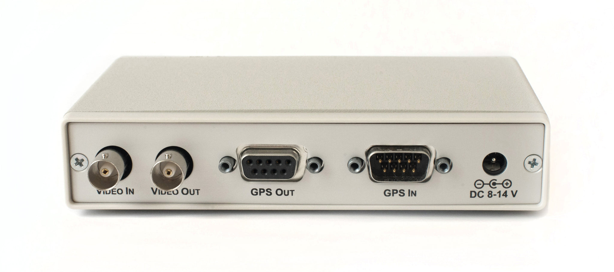
Connections:
GeoStamp® HD has five connectors
| Connector | Hookup |
| VIDEO IN (optional) |
|
| VIDEO OUT |
|
| SERIAL IN |
|
| SERIAL OUT |
|
| DC IN |
|
Dip Switch Configuration:
GeoStamp® HD has 8 internal DIP switches. To access the DIP switches disconnect all cables from the GeoStamp® HD unit then remove the 2 screws from the rear of the enclosure. The rear panel and bezel with the circuit board will slide out.
| DIP # | Description |
| 1 - 6 | Reserved |
| 7 | Factory Reset OFF = Normal Operation ON = Factory Reset |
| 8 | Firmware flash update OFF = Normal operation ON = Firmware flash mode |
Operation:
- Apply power to the GeoStamp® HD. During power-up the yellow “GPS Fix” LED will blink for 10 seconds.
- An on-screen “X” icon appears if there is no valid communications with the external GPS receiver
- An on-screen “?” icon appears if there is a valid connection to the external GPS receiver but no satellite fix
- The on-screen GPS fields will update after each valid NMEA GPRMC, GPGGA, and SBDBT sentence is received from the external GPS receiver. The yellow “GPS Fix” will illuminate.
- Press the MENU button to enter the on-screen menu configuration (see below)
- Simultaneous press the UP/DOWN buttons to configure the incoming video input source (see below)
Configuring the incoming video source:
- The GeoStamp® HD unit must be configured to match the incoming video input source (AHD, HD-TVI, and HD-CVI 720p or 1080p)
- To match the incoming video input source press and release the UP/DOWN buttons simultaneously to cycle through the video options until stable text is visible on-screen (you will see an on-screen menu)
- Press the ENTER button and wait until for the normal operation screen
- The configuration information is stored in non-volatile memory so information is retained even with loss of power to GeoStamp® HD
Status Icon:
If the “Show Status” option is enabled (by default) the following icons may appear:
| Icon | Status |
|
X
|
No or invalid communications with the attached GPS receiver |
|
?
|
The attached GPS receiver does not have a satellite fix |
“GPS Fix” LED:
The “GPS Fix” LED illuminates when the attached GPS receiver has a fix with a minimum of 4 satellites. A GPS fix is required for on-screen GPS information to update.
On-Screen Menu Configuration:
At any time press the MENU button to enter the on-screen menu configuration. The UP, DOWN, and ENTER buttons move the cursor and change the settings. All configuration information is stored in non-volatile memory so information is retained even with loss of power to GeoStamp® HD.
Main Menu:
|
Menu Option |
Action / Setting |
| Enable GPS Overlay | OFF = Display the overlay text ON = Pass video through without displaying the overlay text |
| Display Options Menu... | Display the Options Menu |
| Field Formatting Menu... | Display the Field Formatting Menu |
| GPS Settings Menu... | Display the GPS Settings Menu |
| Save Changes and Exit | Save changes and exit the Main Menu |
| Discard Changes and Exit | Discard changes and exit the Main Menu |
Display Options Menu:
| Menu Option | Action / Setting |
| Screen Layout | On-screen GPS field layout formats
|
| Show Status |
|
| Show Altitude |
|
| Show User Msg |
|
| User Message | Enter an optional 10 character on-screen message
|
| Download Custom Layout | Future enhancement |
| Main Menu | Return to Main Menu |
Field Formatting Menu:
| Menu Option | Action / Setting |
| Altitude | Altitude Formats
|
| Speed | Speed Formats
|
| Heading | Heading Formats
|
| Date | Date Formats
|
| UTC Offset | Time offset from UTC (-12 through +12) e.g. -5 is EDT
|
| Main Menu | Return to Main Menu |
GPS Settings Menu:
|
Menu Option |
Action / Setting |
| Baud Rate | External GPS receiver baud rate (4,800 - 38,400) |
| Override Alt With Depth | OFF = Display altitude ON = Display depth to transducer |
| Diagnostics... | Display GPS diagnostics screen |
| Main Menu | Return to Main Menu |