


Description:
OSD-ID+™ is a single channel, standalone static character and graphic composite video overlay circuit. This user programmable device can display up to 30 columns by 12 rows (NTSC) or 15 rows (PAL) of text and imported graphics such as logos directly onto an incoming composite video source. If no video input source is available then OSD-ID+™ overlays text and graphics onto a self-generated background screen. The overlay can be configured to always display, appear on a configurable timer (e.g. every 10 minutes for 30 seconds), or appear on an external button press.
Included with OSD-ID+™ is font editing software. OSD-ID+™ firmware upgrades are supported via a PC connection.
Specifications:
- Dimensions: 2.5" L x 2.5” W x .7" H
- Weight: 0.9 oz.
- RoHS compliant: Yes
- Input voltage: 7.0 to 14.0 volts DC (150 ma max.)
- Operating temperature: -40C to +85C (extended temperature range standard)
- Text area: 30 columns by 13 rows (NTSC) or 16 rows (PAL) Due to monitor over-scan a minimum of 26 columns and 12 rows (NTSC) or 15 rows (PAL) are visible
- Character set: 256 definable characters. 12 x 18 pixels per character. Black, white, and transparent color.
- Character attributes: Blinking, inverted, and background frame
- Graphic sprite max size: 27,648 pixels (e.g. 162 x 162 pixels)
- Video format: Composite video
- Video level: 1 volt peak to peak
- Video impedance: Input 75 ohm, output 75 ohm resistively terminated
Installation:
Solder Pads:
Connecting Solder Pads:Solder Pads: +12VDC (J1)
| Pad | Description |
| +12VDC | 7.0 to 14.0 volts DC input |
| GND | Ground |
Solder Pads: SERIAL (J2) – Only required for font and sprite updates
|
Pad
|
Description |
| OUT | OSD-ID+™ serial output (PC hookup attach to female DB-9 pin 2) |
| GND | Ground (PC hookup attach to female DB-9 pin 5) |
| IN | OSD-ID+™ serial input (PC hookup attach to female DB-9 pin 3) |
Solder Pads: VIDEO IN (J3)
|
Pad
|
Description |
| VIDEO IN | Video Input (optional) |
| GND | Ground |
Solder Pads: VIDEO OUT (J4)
|
Pad
|
Description |
| VIDEO OUT | Video Output |
| GND | Ground |
Solder Pads: External Buttons (P1)
Note: P1 solder pad block is wired in parallel to the Up, Down, Left, and Right buttons
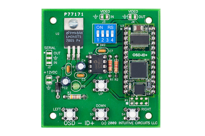
Dip Switch Configuration:
OSD-ID+™ comes from the factory configured for NTSC video format. To re-configure settings OSD-ID+™ has 4 internal dip switches.Note: DIP switch inputs are only checked during power-up.
| DIP # | Description |
| 1 | UNUSED |
| 2 | UNUSED |
| 3 | NTSC or PAL video format OFF = NTSC ON = PAL |
| 4 | Firmware flash update OFF = Do nothing ON = Enter OSD-ID+™ firmware flash update |
On-Screen Menu Configuration:
During normal operation press the Left + Right buttons simultaneously to enter the on-screen menu configuration.The Up and Down buttons move the menu selection cursor up and down. The Right button performs the action of the selected menu item. All configuration information is stored in non-volatile memory so information is retained even with loss of power to OSD-ID+™.
Main Menu
| Menu Option | Action / Setting |
| Overlay | Enable the on-screen overlay
|
| Screen Editor... | Enter the screen editor (see below) |
| Options Menu... | Display the Options Menu (see below) |
| Sprite Selection Menu... | Display the Sprite Selection Menu (see below) |
| Download From PC... | Display the Download Menu (see below) |
| Adjust Screen Position... | Adjust the screen position horizontal and vertical pixel offsets (see below) |
| Save Changes and Exit | Save changes and exit the Main Menu (hour glass appears during save) |
| Discard Changes and Exit | Discard changes and exit the Main Menu |
Options Menu
| Menu Option | Action / Setting |
| Overlay Mode | Overlay mode
|
| Display Every __ Minutes | How often the text and graphics overlay is displayed if the “On Timer” mode is selected (01 - 99 minutes) |
| Display For __ Seconds | How long the text and graphics overlay is displayed if the “On Timer” mode is selected (01 – 60 seconds) |
| Display Instructions | Display instructions when entering screen editor, adjusting screen position, etc.
|
| Clear Screen | Clear the entire screen with spaces |
| Main Menu | Return to the Main Menu |
Sprite Selection Menu
Graphic images (such a logos) can be imported to create on-screen sprites using the font editor utility. A sprite is assigned to a range of characters in the font. Please see the font editor for details.
| Menu Option | Action / Setting |
| Draw Sprite | Draw a graphic sprite on-screen. Sprites are configured in the font editor.
|
| Sprite # | Sprite number to draw (0-15) |
| Horz Position | Horizontal screen position to draw the sprite
|
| Vert Position | Vertical screen position to draw the sprite
|
| Main Menu | Return to the Main Menu |
Download Menu
| Menu Option | Action / Setting |
| Download Font/Sprites... | Download font and sprites using the font editor utility |
| Download Screen Layout... | Download the screen layout using the optional PC screen layout utility |
| Main Menu | Return to the Main Menu |
Screen Position Adjustment Instructions
| Button(s) | Action |
| Left | Move the screen left one pixel |
| Right | Move the screen right one pixel |
| Up | Move the screen up one pixel |
| Down | Move the screen down one pixel |
| Up + Down | Reset screen offsets to default positions |
| Left + Right | Save screen position adjustments and exit |
Screen Editor
The four button keypad allows users to program the screen overlay information with up, down, left, and right cursor movements. The tables below explain the button press combinations and actions.
Screen Editor Commands
| Button(s) | Action |
| Left | Move the cursor left one position |
| Right | Move the cursor right one position |
| Up | Move the cursor up one position |
| Down | Move the cursor down one position |
| Left + Right | Enter character entry mode (see below) |
| Up + Down | Select character attribute settings (see below) |
| Up + Down + Right | Set the current character attributes (e.g. blinking) |
| Down + Left | Copy current character to the clipboard |
| Down + Right | Paste the character from clipboard and advance to the next cursor position |
| Up + Left | Shift the entire line that is right of the cursor left by 1 column |
| Up + Right | Shift the entire line that is right of the cursor right by 1 column |
| Up + Down + Left + Right | Exit the screen editor |
Character Entry Mode Commands
| Button(s) | Action |
| Up | Cycle through the character set (ascending) |
| Down | Cycle through the character set (descending) |
| Right | Save character and advance to next cursor position |
| Up + Down | Erase character with space and advance to next cursor position |
| Left + Right | Exit character entry mode |
Character Attributes Settings
| Menu Option | Action / Setting |
| Blinking | Character blinking state
|
| Background Frame | Character background frame state
|
| Inverted | Character invert state
|
Default Font:
Below is the default OSD-ID+™ font. Use the supplied font editor software to modify or create your own font and graphic image sprites (e.g. logos). Do not modify the empty character at position 0. It is recommended to not remove the characters highlighted in red. These characters can be modified but they are used in the OSD-ID+™ on-screen menu configuration.
Trouble Shooting Tips:
| Problem | Solution |
| Green LED off (unit won’t power up) |
|
| On-screen text and graphics skewed |
|