


Description:
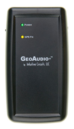
GeoAudio+ with built-in GPS receiver encodes GPS location, heading, speed, altitude, date, and time into a continuous audio stream that can be recorded by off-the-shelf camcorders and DVR (digital video recorder) systems. The encoded audio, automatically synchronized with the camera video, translates into an exact, permanent record of when and where the events in the video occurred.
GeoAudio+ decode mode is used during the video playback to convert the encoded audio back into a GPS NMEA 0183 USB serial stream that can be used by most PC mapping applications such as Google Earth.
GeoAudio+ includes a 6’ 3.5 mm male-to-male audio cable, 6’ USB A-Male to Mini-B cable, Microsoft Windows USB driver and diagnostic application disc. 4 AA batteries are not included.
Specifications:
- Dimensions: 4.25" x 3.50" x 1.25"
- Weight: Without Batteries: 3.9 oz., with 4 AA Batteries: 7.3 oz.
- Input Voltage: 5.0 VDC via USB connector, 6.0 VDC via 4 AA batteries
- Operating Temperature: -40 C to +85 C
- Audio Modulation: FSK
- Audio Output Level: -10dB +/- 1dB
- Audio Input Level Range: -40.0 to -8.0 dBV
- Acceptable Audio Signal to Noise Ratio: 20.0 dB
- Audio In/Out 3.5mm Stereo Jack:TIP - Left audio channel, RING 1- Right audio channel RING 2 - Ground
- USB Jack: Mini-B
Internal GPS Receiver Specifications:
- Receiver: L1 C/A code, 65-channel
- Position Accuracy: 2.5 meters CEP
- Velocity Accuracy: 0.1 meters/sec
- Time Accuracy: 300ns
- Startup Time: 29 second warm/cold start under open sky (average)
- Sensitivity: -161dBm tracking
- NMEA sentences: GPRMC and GPGGA
- Update Rate: 1 Hz (once per second)
- Dynamics: 4G (39.2m/sec2)
- Operational Limits: Altitude < 18,000 meters and velocity < 515 meters/sec (simultaneously)
GeoAudio+ includes an internal GPS antenna. An external GPS antenna version of the product is also available.
External Antenna (optional): Active, 3.3 or 5.0 Volts DC with gain up to 30dB and noise figure less than 2db. Male SMA connector.
GeoAudio+ Configuration
GeoAudio+ has an internal 4 dip switch configuration, audio channel selector jumper, and encoding audio output level adjustment. GeoAudio+ comes preconfigured for normal operation. No additional configuration changes are required.To reconfigure the GeoAudio+ standard configuration disconnect all power to the unit. Carefully remove the 4 case screws (two of the screws are accessible after removing the battery cover). Carefully pull the top and bottom of the case apart so not to put strain on the battery wires.
Dip Switch Configuration:
| DIP # | Description |
| 1 | USB Baud Rate:
OFF = 4,800 baud (default)ON = 9,600 baud |
| 2 | Diagnostic Mode:
OFF = Normal operation (default)ON = Generate 100 lines of test FSK audio data |
| 3 | Raw Debug Mode:
OFF = Normal operation (default)ON = GPS NMEA data sent directly out USB port instead of |
| 4 | Firmware Flash Upgrade:
OFF = Normal operation (default)ON = Firmware flash mode |
Audio Channel Selector Jumper:
| JP1 | Description |
| L | Audio encoded/decoded on left channel (default) |
| R | Audio encoded/decoded on right channel |
Encoding Audio Output Level Adjustment:
The encoded audio output level of GeoAudio+ can be adjusted via the output level potentiometer VR1. GeoAudio+ supports microphone to line level output. (Tick #5 of #11 is default.)GeoAudio+ Power:
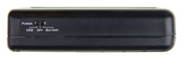
Figure 1.0 – Power selection switch
GeoAudio+ Cable Hookup and Operation
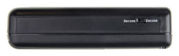
GeoAudio+ has two operating modes Encode and Decode:- Encode mode is used during the video recording process to encode the GPS information onto the camcorder or DVR (digital video recorder) left or right audio track
- Decode mode is used during the video playback to convert the encoded audio back into a GPS NMEA serial stream that GPS mapping software recognizes. During decode mode the yellow GPS Fix LED will blink.

Figure 2.0 – Mode selection switch
Encode Mode (Recording) Cable Hookup:


Figure 4.0 – DVR Recording Hookup
Encode Mode (Recording) Operation:
Decode Mode (Playback) Cable Hookup:
- Option #1 (see Figure 5.0) - use the supplied 6’ 3.5 mm audio cable and 6’ USB A-Male to Mini-B cable to connect GeoAudio+ to the user’s PC.
- Option #2 (see Figure 6.0) - use the supplied 6’ 3.5 mm audio cable and 6’ USB A-Male to Mini-B cable to connect the camcorder, GeoAudio+, and the user’s PC.
- Option #3 (see Figure 7.0) - use the supplied 6’ 3.5 mm audio cable and 6’ USB A-Male to Mini-B cable to connect the DVR, GeoAudio+, and the user’s PC.


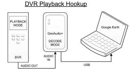
 Figure 7.0 – DVR Playback Hookup
Decode Mode (Playback) Operation:
The yellow GPS Fix LED on the top of the case will blink during decode mode. For PC operations please see the following sections for USB device driver installation and mapping software configuration. Once the USB device driver has been installed then PC mapping applications such as Google Earth can be used to view when and where the events in the video being played back occurred.
The proper playback audio level must be set for reliable GPS decoding. Start with a low output level then increase until reliable decoding occurs. DO NOT TURN THE VOLUME TO MAX!
GeoAudio+ Windows USB Device Driver and Diagnostic Utility Installation
A USB software device driver must first be installed on a Microsoft Windows® PC before GeoAudio+ can interface with PC applications. GeoAudio+ includes a disc with the Microsoft Windows® USB device driver and GeoAudio+ Diagnostic Utility. Please contact us for information regarding Linux and MAC OS X driver installation.
USB Device Driver:
To install the GeoAudio+ USB driver insert the supplied disc and run CDMxxxxx_Setup.exe. If there are no error messages then the device driver was installed correctly.
The first time GeoAudio+ is connected to the PC and powered on Windows should display two messages “Installing device driver software” followed by “Your device is ready to use.”
GeoAudio+ Diagnostic Utility Installation:
The GeoAudio+ Diagnostic Utility (see Figure 8.0) is a tool for verifying that the GeoAudio+ is connected to the PC properly and decoded GPS information is being received. GeoAudio+ Diagnostic Utility is not required to use GeoAudio+ but helpful for troubleshooting. To install the GeoAudio+ Diagnostic Utility insert the supplied disc, run setup.exe, and follow the installation instructions.
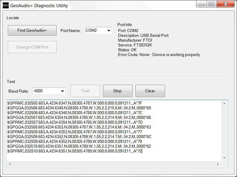
Figure 8.0 – GeoAudio+ Diagnostic Utility
Mapping Application - Google Earth
GeoAudio+ can interface with most GIS (geographic information system) mapping applications such as Google Earth. Google Earth requires a 4,800 baud rate so confirm GeoAudio+ is configured for 4,800 baud (see Dip Switch Configuration above).
The supplied GeoAudio+ virtual COM port software driver causes the GeoAudio+ USB device to appear as a PC serial COM port. Mapping software such as Google Earth can access the GeoAudio+ USB device in the same way as it would access a standard PC serial COM port attached to an external GPS receiver.
To access Google Earth GPS real-time mapping functionality go to the Google Earth’s menu bar option “Tool” then select “GPS.” From the “GPS Import” window (see Figure 9.0) select the “Realtime” tab. The “protocol” option must be set to NMEA.
Once the “Start” button is clicked then Google Earth will search for valid serial COM Ports. Once the GeoAudio+ serial COM Port is found (GeoAudio+ must be decoding data at that time) then Google Earth will begin updating the map.

Figure 9.0 – Google Earth - GPS Import Window
Trouble Shooting Tips:
| Problem | Solution |
| Green POWER LED off (won’t power up) |
|
| Yellow GPS Fix LED off while in Encode mode |
|
| Mapping software not updating GPS real-time position |
|